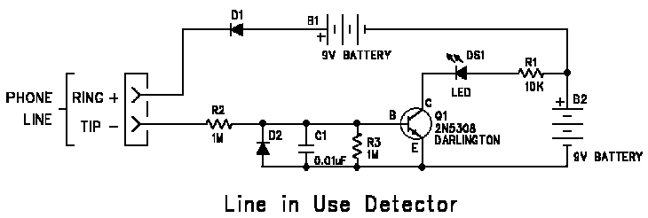
| Telephone Interface Circuits Line In Use Detector This circuit will light an LED when any telephone on the line to which it is connected goes off-hook. The circuit is battery powered, uses few components and can be built into a standard 2" X 2½" plastic modular connector base board block using point to point wiring.
|
||||||||||||||||||||||||||||||||||||||||||||||
| Operation: When all phones are on-hook (no phone in use), the telco's 52V central office battery will reverse bias D1 allowing R3 to hold Q1 and the LED turned off. When a phone goes off-hook (phone in use) then the voltage across the line at the telephone end will drop to 5-15V. This will will allow the 18V battery to forward bias D1 through the phone allowing base current to flow in Q1, thus lighting the LED. Capacitor C1 provides bypass for RF signals, which can cause the LED to illuminate improperly
Parts List:
1. The circuit requires (2) two 9V batteries. This is because the total supply voltage must be greater that the off-hook phone line voltage by enough to provide sufficient base current to turn on Q1. Phones with relatively high DC resistance may not light the LED when battery, B2 is weak. 2. The connection to the phone line is polarity sensitive. If connected incorrectly, the LED will always remain on. The RING lead of the phone line is (+) positive relative to the TIP lead. Battery Notes: 1. B1 is used only to provide base bias for Q1. Battery life for B1 should be almost the shelf life of the battery. B2 provides both base bias and power for the LED. Battery life for B2 depends on off-hook usage but should be greater that 1000 hours of LED illumination for most commonly available 9V alkaline batteries. 2. The circuit shown above will result in just under 1mA of LED drive current, so a high efficiency LED is indicated. You can decrease the value of R1 to increase LED brightness, at the expense of B2, battery life. 3. An alternative method to secure higher LED brightness is to replace B1 with (2) two 9V batteries in series and to replace B2 with (2) two D cells (1.5V ea) in series. Change R1 to 100 ohm. This will result in 10mA of LED current. You should not have to change the 9V batteries. The two D cells should give over 2000 hours of LED illumination. 4. The use of an AC power supply, instead of batteries, may cause degraded telephone performance depending on the nature of possible ground paths in the supply. Usually this is a function of the isolation characteristics of the power supply ac line transformer. Disclaimer: It is a violation of FCC Part 68 rules to connect an uncertified device to the Public Switched Telephone Network. This circuit is intended for use on private analog telephone systems.
|
