CT4811
Sound Card
Audio Interface Characteristics
- Creative Technology Sound Card
CT4811 SB128/PCI SN: 8521
- Creative Technology Ensoniq Audio PCI Mixer
- Microsoft Volume Control (mixer)
- Slider Position Definition:
The Windows Mixer is also called the Microsoft Volume Control. Moving any slider on either the Ensoniq or the Windows Mixers causes the corresponding slider on the other mixer to also move to the same relative position.
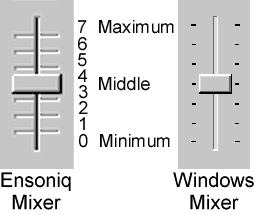
- Except as noted, all measurements were made at 1KHz and with Sliders set to Middle.
- All measurements were made on the Left Channel. A spot check of the Right Channel showed identical results.
- Nominal "LINE" Level for component stereo equipment is about 200mV. This is about 27dB below clipping for the sound card's Line Input.
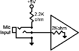
- Mic Input Z:
- 2040 ohms @ 20Hz & 1KHz
- 1420 ohms @ 20KHz
- Mic Input R:
- 2180 ohm
- Mic Boost:
- +20dB gain
- With Mic Boost disabled, clipping is at 0.955V input with Mic Slider Position = Middle
- Input Z & R are the same with or without Boost
- Mic Input Connector:
- 1/8 inch (3.5mm) stereo phone jack
- Tip contact is Mic Input
- Ring contact is +5V mic bias
- Sleeve contact is ground
- The Mic Input jack is red
Mic Input
Level |
Mic Input Slider |
Line
Output for |
||
| V input -------- 0.040 0.056 0.067 0.079 0.094 0.133 0.161 0.161 no output |
dBV input ------------ -28. -25. -23.5 -22. -20.5 -17.5 -15.5 -15.5 |
Position ---------- 7 Max 6 5 4 3.5 Mid 3 2 1 0 Min |
V output ---------- 1.366 0.972 0.818 0.688 0.578 0.408 0.289 0.101 no output |
dBV output -------------- +2.75 -0.25 -1.75 -3.25 -4.75 -7.75 -10.75 -20.0 |
|
||||
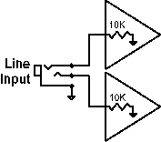
- Line Input Z:
- 12.9K ohms @ 20Hz & 1KHz
- 9.3K ohms @ 20KHz
- Line Input R:
- 13.63K ohm
- Line Input Connector:
- 1/8 inch (3.5mm) stereo phone jack
- Tip contact is Left Line Input
- Ring contact is Right Line Input
- Sleeve contact is ground
- The Line Input jack is blue
Line
Input Level |
Line Input Slider |
Line
Output for |
||
| V input -------- 2.34 3.27 3.91 4.35 4.44 4.60 4.60 4.60 no output |
dBV input ------------ +7.5 +10.25 +11.75 +12.75 +13.0 +13.25 +13.25 +13.25 |
Position ---------- 7 Max 6 5 4 3.5 Mid 3 2 1 0 Min |
V output ---------- 0.566 0.404 0.341 0.287 0.242 0.171 0.120 0.042 no output |
dBV output -------------- -5.0 -7.75 -9.25 -10.75 -12.25 -15.25 -18.5 -27.5 |
|
||||
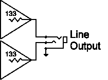
- Source Z: 133 ohms
- Clipping: 4.6V (+13.25 dBV) output
- Line Output Connector:
- 1/8 inch (3.5mm) stereo phone jack
- Tip contact is Left Line Output
- Ring contact is Right Line Output
- Sleeve contact is ground
- The Line Output jack is green
| Lynn Ashley | 28 July 2003 |